Manufacturing Process
|
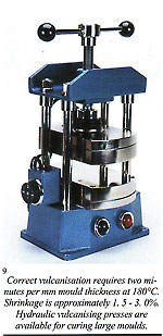
Preparation of a mould using silicon rubber In recent years, the use of elastomer silicon mould rubbers with the consequent elimination of release agents (liquid or tale) and their high flexibility, good memory, durability and excellent properties of detail reproduction, has significantly improved the quality of wax patterns. There is a definite time saving in not using release agents and dangers of inclusion of these materials in the wax, which tend to inhibit filling of finer sections such as ring claws, are eliminated.
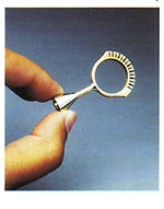
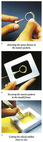
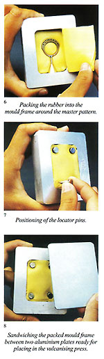
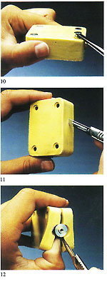
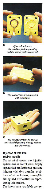
Figure 3 shows an example of a sprue former soldered to the master pattern and placed within the unvulcanised rubber to form the mould entry. Use of silicon rubber moulds with traditional pressure injectors necessitates the moulds to be vented in the normal manner with a scalpel. These are not necessary if a vacuum wax injector is employed. The sequence of photographs shows the simple operations involved and. also the practicality of using locator pins to simplify the register of the mould halves and assist in preventing "parting lines" due to imperfect location (fig 2).
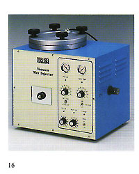
Injection of wax into rubber moulds The advent of vacuum wax injection systems has, in recent years, largely superceded oldfashioned pressure injectors with their attendant problems of air inclusions, incomplete filling and difficulties in reproducing thin sections. The latest units available are extremely reliable and accurate.
This, together with the injection period, is controlled electronically by a compact circuit board which also regulates wax chamber and nozzle temperatures. The rubber mould is offered to the injector nozzle. The mould is then evacuated for one or more seconds and then the wax immediately injected. It is obvious that, under these conditions, the production of perfect waxes is automatic and high production rates of quality wax patems are achievable.
defects in the finished castings, usually during surface treatment (fig. 18). These defects are frequently wrongly identified as porosity,
The vacuum injection process may be farther enhanced by the addition of an automatic clamping and feeding system, which clamps the mould, offers it to the nozzle during the vacuum/injection cycle and then re ts when injection is completed, final y unclamping after solidification fig. 19).
Sprueing of wax patterns and some notes on the metaHurgy of the process
Melting is an extremely traumatic condition for any metallic alloy and, to restore its original, pre-melt, condition, it is essential that, during solidifaction, it recreates its original crystalline structure. A brief explanation here may be of interest. A typical gold alloy is composed of many billions of atoms of gold, silver, copper and other consitutants. When the alloy is a solid, all of these atoms are bonded together in a fied relationship, but not stationary. If imaginary lines are drawn joining the centres of each atom, regular geometrical shapes are the result; this is known as the crystalline structure. One can imagine this in casting ? good or bad ? depend exclusively on the subsequent solidification, which can broadly be compared to the freezing of water. Solidification, or freezing, starts from the walls of the container and progresses towards the centre. At a certain point in this process it is thus possible to identify a solid phase, a liquid phase and a viscous phase. Impurities in particle form tend to be progressively pushed towards the section which solidifies last. As the melt cools, solidification develops throughout the liquid mass as groupings of crystals in three dimensions, propagating in fir?tree and the waxes should be checked to ensure that they are free of these surface inclusions. When using vacuum injection nhance the quality and reliability the form of adjacent cubes with an f the casting process, but very atom at each comer (figs. 20 & 21). ttle regard has been paid to the As previously stated, the atoms are rocess of solidification of the not stationary but in a permanent
tationary. page 23
Figures 23 and 24 depict the external face of the alloy in solid black, the solidifying sections in small squares and the still liquid section in white. As the dendrites grow they broaden and form a myriad of microscopic islets which, upon solidification, weld together forming a granular structure which may be clearly observed under a microscope. Each granule represents a section of the alloy which has solidified crystallising in a given direction. The left?hand section of figure 25 depicts an equiaxial dendrite; the right?hand section depicts a columnar dendrite. Figure 26 shows a typical microscopic view of metallic granular configuration. If cooling of the metal after casting does not occur in a well?defined direction, irregular faults will inevitably occur in the component. We will now examine this process on the microscopic (as opposed to atomic) level. The black portion of figure 26 shows the growth of dendrites forming the grain structure. Very small inclusions or impurities are about to be trapped and the empty spaces will become typical voids or porosity.
section which is still liquid. If contamination of the melt has occurred during the melting/casting process by foreign bodies, oxides or gaseous inclusions, these will remain trapped between the grains at point of solidification and degrade the metallurgical characteristics of the component that has been thus badly cast These contaminants will nersist through any subsequent remelting of the material.
1) Heat diffusion 2) Contamination during melting/ casting 3) Formation of the various phases 4) The number of initial nuclei of crystallisation 5) The type of dendritic growth (columnar and equiaxial).
A ? The component is continuously as c anges in qui to so B ? Solidification takes place uniformly and gradually.
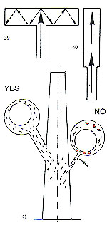
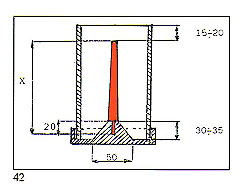
Immense importance attaches to the dimensional relationships of the centre sprue or base and the individual sprues or runners connecting them to the patterns. The fact that must be borne in mind is that the metal within the feeder system remains liquid longer than that in the patterns. It is interesting to consider here the case of dental lost?wax castings where porosity is absolutely inadmissable due to possibilites of ingress of bacteria and other micro?organisms. Figure 28 shows the size of the feeder system provided for casting relatively small toothshaped patterns. It is necessary to remember that the vast majority of alloys melt and sol? idify over a range of temperatures. Diagrams in figure 29 show the cooling curves of some gold/silver (Au?Ag) alloys indicating the respective "heatsoaking interval". Point "S" indicates the start of sol idification while point "F" marks completion of solidification. Fine gold and fine silver solidify at a precise temperature, whereas their various alloys solidify within a ?ange of temperatures known as the ’heatsoaking interval" or "melting .?ange". The contraction from liquid o solid is represented in figure 30 xhich also depicts the progressive eduction of the mass during tem)erature variation. 1 . By contraction at liquidus (from )oint "D" to point "C" we mean the eduction of the metal mass when )assing from casting temperature to ?netting temperature. Casting tem)efuture is always higher thari melting emperature otherwise the molten rietal will not have sufficient fluidity o fully occupy the mould. rhere can be a difference between hese temperatures of 50’C ? 150’C lependent upon the type of alloy ind the type of item to be cast. 2 . Heatsoaking contraction (point ’C" to "B") takes place during the nterval from casting temperature to netting temperature. This phase indergoes the greatest mass reducion and thus requires the maximum ittention. 3. Contraction in the solid state point "B" to point "A") takes place vhen the solidified mass cools town to ambient temperature from olidification temperature "B". rhese contraction processes may ause voids in the cast patterns inown as "shrinkage porosity" vhen these are relatively massive nd "microporosity" when small ind dotlike. Diffuse microporosity mmediately sub?surface are prouced by inclusions of air or gas enerated by investment and trapped hiring solidification. More attention o this phenomenon will be given iarther on. The contraction process as such a strong bearing on the ultinate quality of the castings that we fraw attention to the following dia,rarns: Figure 31 shows the manner in which shrinkage porosity forms after mass contraction if the solidifying casting is starved of farther molten metal. Figure 32 shows the solidification process within a correctly fed mould. The sprueing system allows adequate feeding during solidification and no porosity results in the cast item.
Another factor of equal importance to the size of the sprue is its location on the cast pattern. As a general rule, the sprue should be attached to the most massive part of the pat tem and provision be made for a reservoir of molten metal to feed thin, remote, sections (fig. 34). If these thin, remote, sections are adequately fed with molten metal, porosity will not be experienced (fig. 35). The foregoing section concerning sprueing principles and techniques is of importance with regard to metal feeding. We shall now examine how to achieve uniform cooling of the casting, from the exterior to the interior. A ? The central stem of the "Tree" at the centre of the flask is the principal thermal reservoir and its size must, thus, be proportional to the
36 ? Incorrect sprucing
B ? It is important that all of the pattems in a given flask are of a similar size, mass and cross?section.
C ? Patterns should be attached to the central stem in a clean, fidy and regular fashion. D ? The overall diameter of the assembled "tree" must be in relation to the internal diameter of the flask. Ideally, there should be a clearance of 10? 15 mm between the outermost patterns and the inside of the flask.
E ? Flask temperature at the moment of casting must be determined by pattern profile.
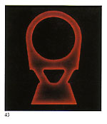
F ? It is desirable that cooling of the molten metal should take place from one side only of the flask, developing in one direction. Our vacuum system built in to the casting arm is of value here, creating suction at the opposite end of the flask to that at which the metal is injected, not only satisfying the foregoing condition, but also removing harmful gases generated by the metal impacting the investment. This point will be dealt with in more detail later. Figure 43 depicts the result of progressive cooling without the harniful phenomena described earlier. It must be home in mind that all of the phases described in this sectionoccur in a very brief interval of time and are influenced by metal temperature, alloy composition, flask temperature, profile of the casting patterns and ? above all ? the method of casting employed. Investment preparation and burnout
Modem investment powders are easy to use and permit the rapid prep INVESTMENT WATER fN GRAMS IN GRAMS HEAVY CASTING 1000 370 aration of good quality moulds. These are mainly formulated from: Silica (Si02)
Common name gypsum. This acts as a "binder" and reacts with water forming gypsum hydrate. Additives or Modifiers These control the setting time and flow characteristics and to reduce the tendency to foam or "rise" during vacuuming. The condition of the investment powder is very critical and can have a strong influence on the quality of the castings produced. The following points should, thus, be noted.
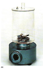
B ? Additives and modifiers con tained in modem powders may disappear after a certain time, altering the characteristics of the material. Shelf life should thus be observed. One result of this can be the appearance of greater fluidity of the investment 46 "slurry". Attempts to correct this by adding more powder to the mix will alter the water?powder ratio from that recommended by the manufacturer and create problems. This is normally I Kg powder to 360?400 grammes or millilitres of water (see chart). Absolute adherence to these proportions is important. C ? Powder should always be added to water, not vice?versa, otherwise a "lumpy" mix will result with pockets of unmixed investment producing weakness in the final mould. Mixing in a modern "under vacuum" mixer takes care of this type of problem, guaranteeing a smooth and homogeneous mix. Equipment of this type is shown in figure 44. D ? After mixing, the slurry is dispensed into the flasks around the wax "trees" and re?vacuumed with vacuum equipment as shown in figure 45. If large?scale operations are envisaged, machines are available which carry out the whole mixing and dispensing process under vacuum. Such a machine is depicted in figure 46. "Work time" ? the time during which the slurry should be kept "on the move" either by mixing, vacuuming or dispensing ? is normally about 9 minutes at 23’C. Water and powder should always be at approximately this temperature. E ? After investing, the flasks should be set aside and not disturbed for at least one hour in the case of small or medium?sized flasks (120 mm diameter x 150 nun) and two hours for larger sizes. They may then be placed in the furnace for dewaxing and burnout. F ? If steam dewaxing is employed, the foregoing rest times should be extended by 50%. If dewaxing dry, the flasks should be placed into a furnace at 200’C, sprue entry downwards. Dewaxing time is about 4 hours for small flasks and six hours for large. G ? Dewaxed flasks should then be transferred into a burnout furnace already at 200’C. They are then fired at a precisely?controlled timetemperature profile in extremely well?ventilated conditions, these being important for the removal of gases such as S02. A clean mould is vital for good quality castings; inadequately fired moulds will react chemically with the molten metal, producing a variety of metallurgical problems. To fiurther assist in this, the flasks should be stacked sprue entry upwards in the furnace. H ? After firing, attention should be paid to the colour of the investment. Correct firing conditions produce a "snow white" effect; incorrect produces grey, which indicates tha curing has been complete and im purities not dispelled. A mould it this condition will certainly produc defective castings. Peak burnou temperature should be checked t( make sure that this is in line with th( investment manufacturer’s recom mendations. It is possible, given this latte circumstances, that the readin~ given by the furnace temperature controller does not correspond to that actually achieved within the flasks, which, being massive it thermal terms, require a fairly long period to either heat up or coo down. Only experience can deter mine whether furnace heating o cooling rates match those of the flasks, and these rates will vary according to whether the flasks are large or small.
This showed clearly that, only after about three hours did the two temperatures finally coincide both on heating and cooling. This was a slightly surprising result and clearly demonstrates that internal flask temperatures "lag" considerably those 48 of the firing chamber. It is, thus, desirable to check the internal temperatures of burned?out flasks using a portable temperature probe (figure 48) at the moment of casting, as this may well vary from the temperature shown by the furnace controller. Curing of flasks is a long and immensely important process and it is essential to employ a programmable microprocessor type furnace time/temperature controller to give the precise curing cycle, which involves: - Furnace switch?on time - Rate of temperature climb to 7500C - Heat soak time at this maximum - Controlled decrease to casting temperature I . The firing chamber of the furnace must be large enough in relation to the charge of flasks to permit adequate ventilation without obstruction; also to allow the insertion of loading tongs. L . Mould temperature at time of casting depends upon the mass, cross section and shape of the patterns and the type of alloy to be cast. For example, pieces in thin section 18 carat alloy should be cast at 620’C while more massive items need to be cast at between 570’C and 520’C.
The chart indicates flask temperatures at point of casting according to the alloy. Temperatures given here refer to medium?sized, ring?type patterns (or bracelet components, small brooches, etc.). Thinner pieces, such as chain links, will probably require the flask temperature to be increased by about 30’C. These temperatures, however, are merely a rough guide; only trials will reveal the optimum temperatures for given components and alloys. With this in mind, a detailed chart listing all the casting conditions employed will prove extremely useful ? particular when it is likely that casting of the identical components is likely to have to be repeated in the future. M ? Due to the permeability of investment, the mould may be evacuated to 100?200 TORR in about 20 seconds whilst on the casting arm, using the vacuuin system built?in to the casting arms of our centrifugal machines (figure 49).
This vacuum is maintained during rotation and injection of the molten metal and eliminates internal resistance to mould occupation due to air pressure ? thus facilitating filling of very fine sections ? and also removes gases causes by the metal impacting the gypsum within the investment ? a common cause of gas porosity. Casting carried out without this feature can have rough surfaces, highly oxidised and frequently brittle.
The ancient process of lost wax casting has always involved rendering metals molten. Modem technology in the form of induction heating is now employed to carry out this function, as opposed to gas torch melting or electrical resistance systems. The melting points of various metals vary widely; for example, tungsten has a melting point of 3,400 C and tin a melting point of 232 C. Melting points of various pure metals which interest us are as follows: Pure metals melted together in various proportions produce alloys which are formed in accordance with specific physical laws. Pure metals have precise melting points - for example, gold melts at 1,063 C and at 1,062 C it is still a solid. By
Some examples: - Melting interval - 910-9550C - Red Alloy Au 585 - Yellow Alloy Au 585 Cu 210 - Melting interval - 830-8350C The exceptions to this are the socalled "eutectic alloys" which do not have a melting range/interval but a set melting point as have pure metals. For example: Cu 28.5% Ag 71.5% Melting Point 770 C Producing gold alloys is best done by adding pre-alloys (e.g. Cu/Ag or Cu/Zn) to already molten gold. The energy source employed for heating and melting should contaminate the metal as little as possible with either gases or solids causing a consequent deterioration in metallurgical and physical properties. Electromagnetic induction is, we firmly believe, the source that best fulfils this requirement. Figures 51 and 52 illustrate this. All metals have induced within them "eddy currents" when placed within the influence of an oscillating magnetic field such as that produced by an induction coil. The metal's electrical resistance to these currents provokes a temperature rise and eventual melting.
The principal advantages of this form of heating are: - Unchanged elasticity, homogeneity and density - Negligeable shrinkage - May be carried out in a reducing atmosphere (to limit formation of oxides) - Short melting time - High purity due to lack of contaminants - Capable of achieving temperatures up to 2,500 C - Silent and clean
We do not wish here to discuss in detail now-superceded methods such as that devised by Solbrigg and Taggart in 1907 where wet asbestos was placed on top of a molten charge of metal which in turn rested on the flask sprue entry of the flask, the steam generated forcing the metal into the mould. Neither do we wish We shall instead look at the systems in current use, namely:
There are approximately 10 manufacturers of jewellery "lost wax" casting machines in the world. We intend to talk about machines of our design and manufacture here. We have recently carried out a series of detailed comparative tests on centrifugal, gravity and vacuum casting systems. These tests were brought with difficulties due to the very short time span of the process of metal injection and solidification (0.5-1.5 seconds) and also due to our pressure and temperature sensor frequently being blocked off by molten metal. The conclusions drawn are described briefly as follows. Centrifugal casting During centrifugation, the pressure acting on the melt depends upon the varying acceleration from rest of the casting an-n. Metal flow commences at a low acceleration after 1.3 seconds, at a rotational speed of 30 RPM. The casting arm has during this interval, moved through about 120'. Pressure on the melt reaches its maximum (about 0.6 bar) after about 2.4 seconds. The occupation of the mould is then complete (figure 53).
Maximum gas/air pressure developed in the mould depends upon the acceleration of the arm; the higher the acceleration the higher the pressure, whose maximum is achieved in between 0.5 and 2.5 seconds from rest. The final maximum speed of rotation has no bearing on the changes in gas pressure, since the pressure rise and subsequent fall have normally occurred before that speed is reached.
Without complicating the picture with mathematical formulae, figure 54 demonstrates the difference in compressive forces acting on molten metal entering the flask. Figure 55 shows a hinged casting arm such as we employ on our larger centrifugal machines, where both the counterweight and the flask/crucible are pivoted in such a manner that, starting from a "Z" configuration, the arm progressively straightens itself as it takes off from rest. Our smaller machines have rigid (non?hinged) arms (machines with a capacity of up to 3 Kg fine gold). In all cases, the arm geometry is determined by considerations of optimum flask length, correct acceleration and terminal rotation.
Crucible design and attitude are also important. Our crucibles rest at an angle of 7' to 10' towards the flask (figure 56) thus enabling the metal flow to commence immediately at the inception of rotation. The size of the molten charge of metal is also important here. Upon entering the flask, the metal immediately encounters an obstacle consisting of air and gases within the mould cavity. Although the fired investment is permeable, these entrapped gases cannot always escape sufficiently quickly by this route and may, thus, be entrapped within the solidifying metal. The effect is comparable to pouring a liquid into a closed container (figure 57) with no exit route for the air within. The mould should, therefore, be evacuated prior to metal occupation and, on our casting arms, this is accomplished by means of a large vacuum pump acting on the rear of the flask immediately prior to and during rotation.
Figure 59 depicts the mould being occupied by the fluid mass under vacuum.
Vacuum-assisted gravity casting
In the preceding section on centrifugal casting, reference was made to the pressure applied to the stream of molten metal. In the case of vacuum casting, we have to consider mould occupation by means of a vacuum acting through the pores of the investment. In practice, we have discovered that the maximum vacuum effect on the metal is achieved at the moment of metal entry - normally after about 0.5 seconds - and then progressively decreases as entrapped gases and air are drawn out.
The higher this rate, the more efficient the occupation or filling, although it has not proved possible to provide facts and figures experimentally due to the relatively slow response time of the sensing equipment currently available. The whole of this process is normally completed in 0.5-1.0 seconds. In practice, this process is generally unsuitable for very fine section and filigree objects, which tend not to fill completely. To assist in filling, we have devised a refinement to the system. A positive pressure is applied to the surface of the melt during casting. This has to be applied at the moment of metal entry; a mere moment later, and this will be ineffective due to the metal having already partially solidified. One major difference between castings produced by this method and those produced centrifugally is in respect of uniformity of density.
Another plus point to this process is that it is not necessary to add additional metal for a sprue "button"; this, thus, reduces the amount of precious metal being recycled with a consequent reduction in "losses".
Investment removal, sprue cutting and finishing operations After casting and quenching residual investment has to be removed from the cast "trees" without affecting surface or mechanical properties and the most efficient way to do this is by means of a high pressure pump within an enclosure. Figure I shows such an enclosure mounted onto a settlement tank for the powder which is thus prevented from finding its way into - and blocking - the drainage system.
The final cleaning-up and investment removal is performed in a suitable ultrasonic cleaner (figure 74). The frequency of such a unit (35 kHz) removes every tiny trace of investment in a remarkably short time.
Casting of platinum and platinum alloys is best carried out by means of high frequency induction melting and centrifugal casting. It is advisable to utilise very small "trees" as platinum tends to solidify quickly and would not fully occupy a large or long cavity. Platinum melts at 1,7731C but it is necessary to elevate the melt to about 2,400'C before attempting to cast. This process must be carried out with the utmost rapidity. Platinum is no friend of silica and borates, so preparation areas for platinum casting must be scrupulously clean and clear of sulphate-bonded investments as used for gold and silver. The specific gravity of the metal is 21.45. Metal to wax ratio is 21-1. Weigh the wax patterns and multiply by 21 to arrive at the weight of the charge of metal. The crucible used must have an extremely high thermal resistance and also be proof against thermal shock. It must also be silica-free. The metal to be cast must be cut into small plates roughly 8 x 8 x 2 mm or rods 7-8 mm diameter x 8 mm. Usually, platinum is alloyed with copper in the proportion 950 Pt + 50 Cu. To render it more suitable for stone setting, it is usually alloyed with Palladium, for wedding rings with cobalt and with tungsten for brooches, springs, findings etc. Platinum should never be used if its purity is uncertain. The melting crucible must be set very close to the flask on the casting arm. Melting occurs in a very short time interval. Quenching into water should be done about fifteen minutes after casting. The phosphate-bonded investment is difficult to remove from the castings and it is usually necessary to use some form of sand or bead blaster for this purpose. Sprue buttons and scrap may be recast with 50% new metal. Precise flask burnout is, once again, very important here. Flasks should first be dewaxed at 200'C for about three hours and then fired in a burnout furnace having a time-temperature profile conforming to that shown on the chart (figure 75). For certain applications, this investment may need to be fired up to 1, 1 OO'C.
Washing of wax patterns prior to investing may seem like obsessive behaviour but is, in fact, vital for optimum results from the process. Casting wax is, to some degree, water repellent and this militates against adequate "wetting" by the investment slurry - leading to surface imperfections on the castings. Anything which can translate the care taken by the modelmaker in the preparation of a perfect master pattern through to a similarly perfect casting is to be regarded seriously and the use of a wetting agent or surface tension reducer is to be throughoutly recommended in this context.
Induction melting permits the use of either graphite or ceramic crucibles. In the case of graphite, great care must be taken to avoid graphite inclusions in the melt. Graphite quality is extremely important and a new crucible should be pre-washed with alcohol to remove graphite powder residual from the manufacturing process. The new crucible should then be coated internally with a wash of lead-free boric acid dissolved in water - using a brush. The crucible rim should also be coated. Make sure that the film thus applied is thin, otherwise borax inclusions within the castings will result.
A - Since the crucible acquires heat by induction from the coil and trans fers this by conduction to the metal, the top half will tend to overheat. B - Inefficient heat transfer from crucible to metal results in a slow melt. C - When the metal reaches liquidus, the mass of the crucible will be at a higher temperature, resulting in distortions to the metallurgical properties of the casting. Ideally, the colour of light emitted by the heated crucible should be similar to that emitted by the metal.
B - Ensure that the crucible lid fits perfectly C - Referring to figure 77, the dotted ine n icates attitu e o t e crucible nozzle with respect to the sprue entry and the sense of rotation. It is necessary to use ceramic crucibles when the alloy has over 25% palladium contents or when platinum or steel has to be molten. Crucible quality is very important: it must not release compounds which may be absorbed by the molten metal. |
||||||||||||||||||||||||||||||

 Silicon rubber cannot be burned after vulcanisation, so every detail has to be built into the master patter beforehand. Minor modifications may, however, be made with a scalpel.
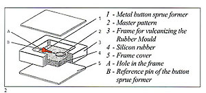
 Pressure is supplied by an air com pressor and a small vacuum puml evacuates the mould, the vacuuminj time being controlled by a secon timer (fig. 16).
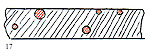 Air inclusions in the centre of wax patterns are generally of no importance but, near the surface, can burst under vacuum and appear as surface
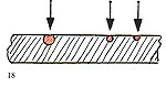
 This is an additional advantage, as these vents frequently produce "finning" on the waxes which have to be removed prior to investing.
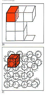 Much time and attention has been spent in considerations of how toenhance the quality and reliability of the casting process, but very little regard has been paid to the process of solidification of the alloys used which is absolutely crucial for the final quality.
 Iloys used which is absolutely state of balanced oscillation, the rucial for the final quality. amplitude of which is elated to the elting is an extremely traumatic kinetic energy of the component ondition for any metallic alloy and, atoms and determines the hardness
 The metallurgical properties of the forms known as "dendrites" (after the acient Greek word for tree). Those that grow in a direction opposite to the diffusion of heat are known as "columnar dendrites" and when growth is irregular and disorderly are known as "equiaxial dendrites".
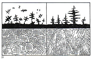 The crosshatched area depicts the
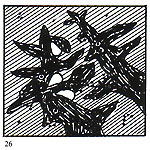 To summarise, good solidification depends on these factors:
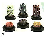 From the preceding, it is quite easy to understand the types of factors that may produce porosity in castings. The causes, excepting contamination (which may be eliminated by taking care not to introduce impurities) are exclusively to do with the manner of cooling and solidification. Therefore, conditions must be established to ensure that:
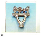 To ensure that the first condition is met, it is always necessary to provide a "thermal reservoir" capable of supplying, without interruption, molten metal during all the progressive contractions of the solidifying component. One may think in terms of a metal feed tank in the centre sprue (in the case of "tree" sprueing) or within the base in the case of "button" sprucing (fig. 27).
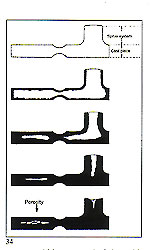 If the sprue size is not adequate to permit continuous feeding until solidification is complete, the results may be as depicted in figure 33.
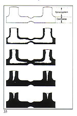 weight and size of the patterns. Some practitioners in this field assert that a tapered form is the most appropriate in order to avoid excessive recycling of precious metal with consequent "losses". Also, hot metal inevitably reached the top of the "tree" first and, thus, the lower part, where the metal arrives at a slightly lower temperature, requires the larger cross?section.
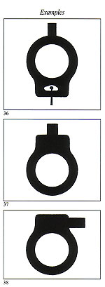
 The use of gypsum?bonded investments poured around wax patterns to create casting moulds is relatively recent compared to the long history of the lost?wax process, and dates from the famous 17th century Florentine goldsmith, Benvenuto Cellini, who devised a gypsum compound.
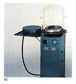 This is combined with a mixture of finely?ground quartz and crystobalite. The latter is a form of quartz with a high thermal expansion designed to match the shrinkage of the molten metal during solidification
 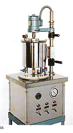 A ? Investment powder has a strong affinity for water and rapidly becomes damp in humid atmospheres. Bags should therefore be kept sealed and dry at all times. Dampness will increase the setting time of the material and considerably weaken it. Surface roughness on the castings can also result ? also "flashing".
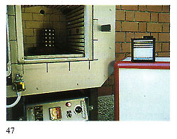 We have carried out tests using a temperature probe (figure 47) inserted within flasks of varying sizes within a burnout furnace. During the burnout cycle, this probe and the furnace instrumentation were connected to a chart recorder and temperatures of the firing chamber and flask interiors recorder on the paper
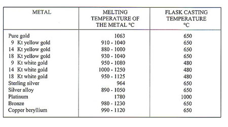
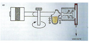
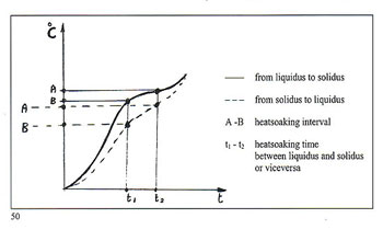
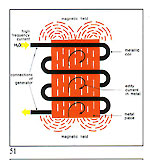
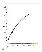
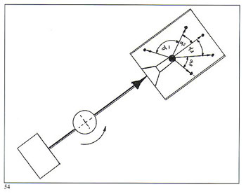
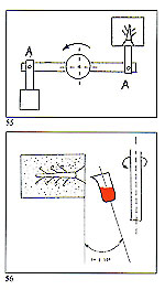
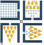 Figure 58 shows the removal of harmful gases during metal entry to the mould. The vacuum is maintained throughout the whole of the period of rotation.
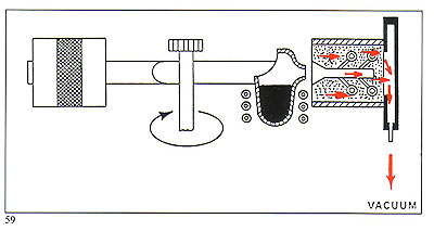
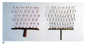 Figure 60 illustrates one of our most convincing tests, where a nylon net of thickness 0.26 min was invested, burned out and metal injected into the cavity left. A sound casting 50 mm long with only one sprue to the base was obtained in 18 carat gold.
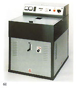 Figure 61 shows a centrifugal casting machine featuring automatic temperature control. Figure 62 shows the interior of the casting chamber of this machine with the flask positioned against the suction backplate of the arm. This machine is capable of performing the entire casting cycle (melting and centrifugation) in less than six minutes, with the melt temperature maintained automatically and featuring the aforementioned vacuum flask extraction system, permitting the casting of extremely fine sections.
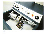 This machine offers the possibility of using either graphite or ceramic crucibles - also a recently-introduced ceramic-lined graphite crucible to eliminate the possibility of graphite inclusions within the melt. Casting of platinum and steels is also feasible with this machine.
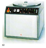 Figure 63 shows our latest "under vacuum" centrifugal unit, where the melting and casting cycle may be carried out entirely in an air-free environment.
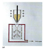 The general scheme of this casting system is depicted in figure 64.
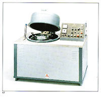 Permeability of the investment mould is obviously an important factor in this process and this is in turn influenced by the water/powder ratio of the investment mix. Tests have demonstrated that a low water content (35%) tends to create mould cracking. A 37% content produces a mould which is insufficiently permeable - even with a high vacuum applied - and a 40% content has been shown to produce a highly permeable mould enabling a more effective vacuum effect to be achieved during the casting process. The rate of increase of this effect and the rate of mould occupation also depends on the external pressure.
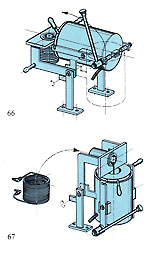 Castings produced centrifugally tend to vary slightly in density due to random forces acting on the metal during centrifugation; this is not the case with the vacuum-assisted gravity method. Also, the constant action of the vacuum on the cooling and solidifying metal tends to produce a gradual and uniform cooling effect, which can be beneficial.
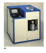 Figure 65 shows a vacuum-assisted gravity casting machine, where the cycle is practically fully automatic. The metal is rendered molten in an inert gas atmosphere - also pouring into the mould, which is evacuated during casting with a heavy-duty vacuum pump. Special systems control metal temperature and pouring (figures 66 and 67) and the machine uses the new ceramic-lined crucible mentioned in the previous system, thus eliminating the possibility of graphite inclusions. This machine will handle all metals apart from platinum and steels.
 The equipment depicted in figure 69 is another approach to vacuum casting, featuring a "bottom pour" crucible with positive pressure above the melt, as previously mentioned. The machine also features a medium-frequency generator and has fully computerised surveillance and control/printout. It is capable of memorising several casting programmes in several languages.
 Parting-off of the cast patterns from the "tree" may be performed using either hand or pneumatic cutters (figure 73).
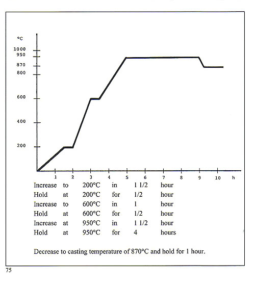
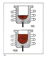 It is desirable to use a crucible matched to the melt size. As a general rule, a crucible should be at least half full. Less than this, and the following adverse consequences will result:
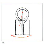 A - Ensure that the sprue system's conical entry is large enough